1. What is DFMEA?
DFMEA (or Design FMEA) stands for Design Failure Mode and Effects Analysis. It is a type of FMEA (Failure Mode and Effects Analysis) that focuses on the design of the product to reduce the risk of product failure.
In other words, DFMEA is an analytical methodology used in the product design and development phase to improve product quality.
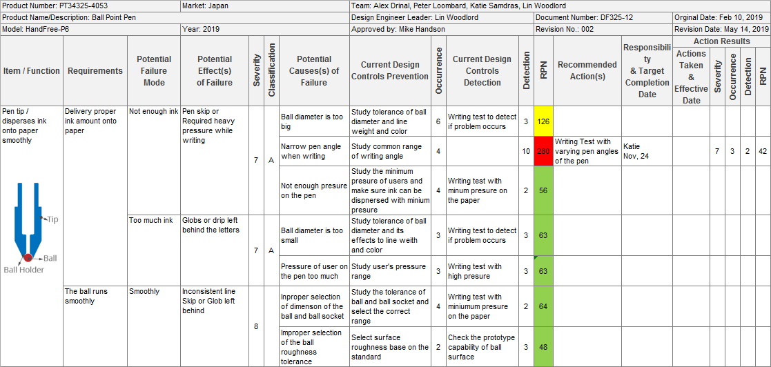
Example: DFMEA worksheet of a ballpoint pen

2. Why use DFMEA?
Quality is critical to customer satisfaction, loyalty, and future product purchases. Recent quality scandals with many companies indicate that serious design problems can ruin the reputation of any company or put them out of business.
Less serious design problems can dissatisfy customers, delay the launch of a new product, and place a substantial financial burden on the company.
In a new product project, design failures are created unintentionally in the Product Design & Development phase. Without DFMEA, almost all failures will not be discovered until validation and trial production, and some will not be detected until after the production launch.
However, the cost of developing countermeasures in the later phase is much higher than in the earlier stages. With DFMEA, countermeasures will be considered at almost the same time that the failures are generated.

3. When to conduct DFMEA
With DFMEA, an organization can ensure that all design requirements are completely met before production launch and maintain design quality later on.
3.1 When to start
For a new product, Design FMEA should start with product design and before prototype manufacturing.
3.2 When to review
The team should continuously review and update the DFMEA document in the event of product changes:
- Change of Product Design: Product change could be the reason to review DFMEA. In this case, the change point and effected points should be focused on.
- Quality Problem caused by product design: New internal defects or customer return should be reflected in DFMEA to review and consider corrective action.
4. Who will conduct DFMEA
A good DFMEA needs to be conducted by the cross-functional team and led by the responsible product design engineer. The involved departments should include but are not limited to Design, Testing Analysis Engineer, Production, Supplier Quality, Product Quality, Service and Logistics.

5. How to conduct DFMEA
5.1 DFMEA Template
First, a DFMEA template (also called a DFMEA form) is needed. Like any other FMEA template, a DFMEA template has two parts: the header and body.
The header provides general information, including, but not limited to, the product name, product number, team member, project leader, customer, document number, and document version.
The body includes many columns that have relationships. There are many different Design FMEA templates that include various column names. Some columns can be separated or combined, but there is no difference in their meaning.
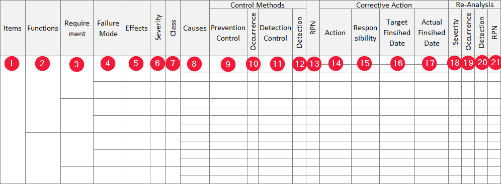
- Items: Item (component, part, assembly) of the product/part to be analyzed. An Item has one or many functions.
- Function: Functions of an item. A function has one or many requirements
- Requirement: Requirements of a function. A requirement has one or many potential failure modes.
- Failure Mode: The way that an item potentially fails to meet the requirement. A failure mode has one or many potential effects.
- Effects: Potential effects of the potential failure mode on the function and customers.
- Severity (S): a ranking number reflects the most severe potential effect of a failure mode. Severity ranks on a 1 to 10 scale, 10 is the most severe risk.
- Class: Special product characteristic or high-risk failure mode.
- Cause: The reason why failure happens. A failure mode has one or many potential causes.
- Prevention Control (in Control Method): Design action to prevent potential cause to occur.
- Occurrence (C): a ranking number reflects the possibility of occurrence of the Failure. Occurrence ranks on a 1 to 10 scale, 10 means the highest possibility of occurrence.
- Detection Control (in Control Method) Design action to detect the failure or the cause of the failure if it happens.
- Detection (D): a ranking number reflects the best detection control method. Detection ranks on a 1 to 10 scale, 10 means worst detection capability.
- RPN: (stands for Risk Priority Number) An indication number to evaluate the risk of the process based on Severity, Occurrence, and Detection. Depend on RPN and S, O, D indexes, the responsible team/individual has to decide corrective action needed for each failure mode. RPN formula is: RPN = S x O x D
- Action: Recommended action to eliminate or reduce the chance of the causes of failure mode.
- Responsibility: Individual person or team/department who has to complete the recommended action.
- Target Finish Date: The plan completion date.
- Actual Finish Date: The actual completion date.
- Severity: re-evaluate severity of failure mode after corrective action
- Occurrence: re-evaluate occurrence possibility after corrective action
- Detection: re-evaluate detection capability after corrective action
- RPN: re-calculate Risk Priority Number after corrective action
5.2 Input of Design FMEA
Below documents should be considered as input resources for the team when conducting Design FMEA:
- Block (Boundary) Diagrams: The block diagram of the product shows the physical and logical relationships between the components of the product. Block Diagram can be used to determine the item included in the DFMEA.
- Parameter (P) Diagrams: The P-Diagram is a structured tool used to describe the physics related to the functions of the design by listing input, output, control, and noise factor of the objective.
- Quality History: Can be used to find the potential failure mode and confirm the effectiveness of preventive action in the new design.
- Drawing, Engineering Specification: Can be used to determine the function and requirements.
- Bill of Materials: List of components/parts of the product.
5.3 Steps to develop Design FMEA
When everything is ready, DFMEA team, template, and support document, you can start conducting Design FMEA by following the 9 steps below:
- Define Product Requirements
- Brainstorming Potential Failure Mode
- Analyze Effects
- Finding Potential Cause
- Describe Current Control for the potential causes
- Evaluate Occurrence /Detection of Current Status
- Calculate RPN and Evaluate Risk
- Corrective Action Plan
- Re-rating RPN after Corrective Action
5.4 Linkage of DFMEA
DFMEA is not a standalone document in the product and process development process. To make sure your DFMEA consistency with each other, the information in DFMEA must link with the respective information in other documents:
PFMEA
The connection between PFMEA and DFMEA may not be obvious because they have different objectives. While PFMEA focuses on the process, DFMEA focuses on the product. However, below linkage should be maintained:
- Characteristics of product and process mentioned in PFMEA should be consistent with corresponding items in DFMEA.
- Sometimes, DFMEA and PFMEA failure modes have the same potential effect. Severity ranks that associate with the same effect should be equal in both PFMEA and DFMEA.
- Potential failure modes of PFMEA leads to product-related effect should appear in Potential Cause of Failure in DFMEA. Vice versa, Potential Failure Mode in DFMEA that cause by the process should appear in PFMEA Potential Failure Effects.
Design Verification Plan and Report (DVP&R)
Design Verification Plan and Report is a plan and report used to confirm a system, product or component meets the design requirements. At the minimum, DVP&R should have test items, criteria, procedures, and sample size. DFMEA prevention and detection control are the input of the test item included in the Design Verification Plan.
6. Summary
DFMEA should reflect the current status of product design, and that is why it is called a living document. However, keep DFMEA “living” is not easy. That’s because of the complicacy of DFMEA and its linkage to other documents. Maintaining DFMEA living is much easier if we use proper DFMEA software as FMEA Analysis.